
A-T Solar fully recognizes that deriving benefit from installing solar systems will ultimately depend on a public that understands how to use the technology. As such, our policy of constant pre sales and after sales DIALOGUE with our customers is central to our approach. This allows us to inform and educate the public how to get the real benefits from solar applications, so that they do not experience “buyers remorse” after purchase, if they are not able to realize expected benefits.
This page will also provide some basic information below about various aspects and products of the technology which will keep customers and interested persons constantly updated and well informed.
CHAPTER 1 – SOLAR PANELS
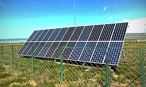 A solar panel or photovoltaic module, is composed of individual PV cells. This crystalline-silicon panel has an aluminiumframe and glass on the front.
 A solar panel or photovoltaic module, is composed of individual PV cells. This crystalline-silicon panel has an aluminiumframe and glass on the front.
 A solar panel (also solar module, photovoltaic module or photovoltaic panel) is a packaged, connected assembly of photovoltaic cells. The solar panel can be used as a component of a larger photovoltaic system to generate and supply electricity in commercial and residential applications.
Because a single solar panel can produce only a limited amount of power, many installations contain several panels. A photovoltaic system typically includes an array of solar panels, an inverter, and sometimes a battery and interconnection wiring.
Theory and construction
 Left – Polycrystalline PV cells connected in a solar panel.
Solar panels use light energy (photons) from the sun to generate electricity through the photovoltaic effect. The structural (load carrying) member of a module can either be the top layer or the back layer. The majority of modules use wafer-based crystalline silicon cells or thin-film cells based on cadmium telluride or silicon. The conducting wires that take the current off the panels may contain silver, copper or other non-magnetic conductive transition metals.
The cells must be connected electrically to one another and to the rest of the system. Cells must also be protected from mechanical damage and moisture. Most solar panels are rigid, but semi-flexible ones are available, based on thin-film cells.
Electrical connections are made in series to achieve a desired output voltage and/or in parallel to provide a desired current capability.
Separate diodes may be needed to avoid reverse currents, in case of partial or total shading, and at night. The p-n junctions of mono-crystalline silicon cells may have adequate reverse current characteristics that these are not necessary. Reverse currents waste power and can also lead to overheating of shaded cells. Solar cells become less efficient at higher temperatures and installers try to provide good ventilation behind solar panels.
Some recent solar panel designs include concentrators in which light is focused by lenses or mirrors onto an array of smaller cells. This enables the use of cells with a high cost per unit area (such as gallium arsenide) in a cost-effective way.
Depending on construction, photovoltaic panels can produce electricity from a range of frequencies of light, but usually cannot cover the entire solar range (specifically, ultraviolet, infrared and low or diffused light). Hence much of the incident sunlight energy is wasted by solar panels, and they can give far higher efficiencies if illuminated with monochromatic light. Therefore, another design concept is to split the light into different wavelength ranges and direct the beams onto different cells tuned to those ranges. This has been projected to be capable of raising efficiency by 50%.
Currently the best achieved sunlight conversion rate (solar panel efficiency) is around 21% in commercial products, typically lower than the efficiencies of their cells in isolation. The energy density of a solar panel is the efficiency described in terms of peak power output per unit of surface area, commonly expressed in units of watts per square foot (W/ft2). The most efficient mass-produced solar panels have energy density values of greater than 13 W/ft2 (140 W/m2).
CHAPTER 2 – OFF GRID SYSTEMS
Off-Grid Solar Energy System (with Battery Backup)
This type of system is for those who truly want energy independence.
It is completely independent of the electric utility grid. It is also very valuable in remote areas where there are no existing power lines. For this reason, off-grid systems are very popular in mountain and forests areas, for cabins or homes that are far away from the electrical grid. It has all of the features and benefits of a standard grid-tied system, but with the additional benefit of uninterruptible power. The battery backup will ensure that you have electricity for critical loads in when the sun is down or blocked by clouds. When the optional backup generator is added, you are truly protected against nearly any catastrophic situation. There is also a optional DC hookup, which means you can use DC appliances and power devices.

Typical off-grid Solar Energy system
How it works:
1) Sunlight hits the solar module, which is attached to your roof with the mounting racks.
2) The solar (or photovoltaic) cells inside the module then convert the light into electricity.
3) This electricity travels through wires to the charge controller, which senses battery voltage and regulates battery charging – the electricity is then used to keep the batteries fully charged to ensure uninterruptible power.
4) The remaining electricity is then transferred to the inverter and/or the load controller (optional, if you want/need DC electricity). 4a) The inverter takes the electricity from the solar module (DC electricity) and converts it into the electricity your home needs to run your appliances, lighting, etc. (AC electricity). 4b) The load controller is used for any DC power device you may want to run, and decreases the energy losses experiences when the inverter converts the DC to AC. Nearly all power devices and common appliances use AC electricity. Although, there are DC power devices available.
5) The AC electricity then travels to a standard AC service panel (breaker box), and is supplied to directly to your home/business. 5a) The DC electricity (optional) then travels to a standard DC service panel (breaker box), and is supplied to directly to the DC loads in your home/business.
6) (Optional) In the event of an emergency (extended cloud cover or unforeseen system disruption), your system automatically begins to draw power from the backup generator and converts it into the electricity you need.
The main components of this system:
- Mounting racks
- Solar modules
- Charge controller
- Inverter
- Battery bank
Types

The two types of stand-alone photovoltaic power systems are direct-coupled system without batteries and stand alone system with batteries.
The basic model of a direct coupled system consists of a solar panel connected directly to a dc load. As there are no battery banks in this setup, energy is not stored and hence it is capable of powering common appliances like fans, pumps etc only during the day. MPPTs are generally used to efficiently utilize the Sun’s energy especially for electrical loads like positive-displacement water pumps. Impedance matching is also considered as a design criteria in direct-coupled systems.
Stand alone system with batteries

In stand-alone photovoltaic power systems, the electrical energy produced by the photovoltaic panels cannot always be used directly. As the demand from the load does not always equal the solar panel capacity, battery banks are generally used. The primary functions of a storage battery in a stand-alone PV system are:
- Energy Storage Capacity and Autonomy: To store energy when there is an excees is available and to provide it when required.
- Voltage and Current Stabilization: To provide stable current and voltage by eradicating transients.
- Supply Surge Currents: to provide surge currents to loads like motors when required.
Hybrid system
The hybrid power plant is a complete electrical power supply system that can be easily configured to meet a broad range of remote power needs. There are three basic elements to the system – the power source, the battery, and the power management center. The power sources are a wind turbine, diesel engine generator, and solar arrays. The battery allows autonomous operation by compensating for the difference between power production and use. The power management center regulates power production from each of the sources, controls power use by classifying loads, and protects the battery from service extremes.
System monitoring
Monitoring photovoltaic systems can provide useful information about their operation and what should be done to improve performance, but if the data are not reported properly, the effort is wasted. To be helpful, a monitoring report must provide information on the relevant aspects of the operation in terms that are easily understood by a third party. Appropriate performance parameters need to be selected, and their values consistently updated with each new issue of the report. In some cases it may be beneficial to monitor the performance of individual components in order to refine and improve system performance, or be alerted to loss of performance in time for preventative action. For example, monitoring battery charge/discharge profiles will signal when replacement is due before downtime from system failure is experienced.
IEC standard 61724
IEC has provided a set of monitoring standards called the “Standard for Photovoltaic system performance monitoring”. It focusses on the photovoltaic system’s electrical performance and it does not address hybrids or prescribe a method for ensuring that performance assessments are equitable.
Performance assessment

Performance assessment involves:
Data collection, which is a straightforward process of measuring parameters, Evaluation of that data in a manner that provides useful information, Dissemination of useful information to the end user.
Load related problems
The wide range of load related problems identified are classified into the following types:
- Wrong selection: Some loads cannot be used with stand-alone PV systems.
- House wiring: Inadequate or low quality wiring and protection devices can affect the system’s response.
- Low efficiency: Low efficiency loads may increase energy consumption.
- Stand-by loads: Stand-by mode of some loads waste energy.
- Start-up: High current drawn by some loads during start-up Current spikes during the start-up can overload the system temporarily.
- Reactive power: The circulating current can differ from the current consumed when capacitive or inductive loads are used.
- Harmonic distortion: Non-linear loads may create distortion of the inverter waveform.
- Mismatch between load and inverter size: When a higher rated inverter is used for a lower capacity load, overall efficiency is reduced.
CHAPTER 3 – GRID TIE INVERTER

 A grid-tie inverter (GTI) is a special type of inverter that converts direct current(DC) electricity into alternating current(AC) electricity and feeds it into an existing electrical grid. GTIs are often used to convert direct current produced by many renewable energy sources, such as solar panels or small wind turbines, into the alternating current used to power homes and businesses. The technical name for a grid-tie inverter is “grid-interactive inverter”. They may also be called synchronous inverters. Grid-interactive inverters typically cannot be used in standalone applications where utility power is not available.
In the United States, grid-interactive power systems are covered by specific provisions in the National Electric Code, which also mandates certain requirements for grid-interactive inverters.
The Jamaican government through the Office of Utilities Regulations (O.U.R.) is currently undertaking negotiations with the Jamaica Public Service Company to arrive at a net metering policy for the country. It is hoped that this new policy will be formulated within coming weeks and not months and will provide sufficient fairness, along with other incentives, for householders to immediately engage with residential solar generation, as has been the case in the USA, Canada and other developed countries.
Typical operation
 Inverters take DC power and invert it to AC power so it can be fed into the electric utility company grid. The grid tie inverter must synchronize its frequency with that of the grid (e.g. 50 or 60 Hz) using a local oscillator and limit the voltage to no higher than the grid voltage. A high-quality modern GTI has a fixed unity power factor, which means its output voltage and current are perfectly lined up, and its phase angle is within 1 degree of the AC power grid. The inverter has an on-board computer which will sense the current AC grid waveform, and output a voltage to correspond with the grid.
Grid-tie inverters are also designed to quickly disconnect from the grid if the utility grid goes down. This is an NEC requirement that ensures that in the event of a blackout, the grid tie inverter will shut down to prevent the energy it produces from harming any line workers who are sent to fix the power grid.
Properly configured, a grid tie inverter enables a home owner to use an alternative power generation system like solar or wind power without extensive rewiring and without batteries. If the alternative power being produced is insufficient, the deficit will be sourced from the electricity grid.
Technology
Grid-tie inverters that are available on the market today use a number of different technologies. The inverters may use the newer high-frequency transformers, conventional low-frequency transformers, or without transformer. Instead of converting direct current directly to 120 or 240 volts AC, high-frequency transformers employ a computerized multi-step process that involves converting the power to high-frequency AC and then back to DC and then to the final AC output voltage. Transformerless inverters, which boast lighter weight and higher efficiencies than their counterparts with transformers, are popular in Europe. However, transformerless inverters have been slow to enter the US market because historically there have concerns about having transformerless electrical systems feeding into the public utility grid. Since the lack of galvanic isolation between the DC and AC circuits could allow the passage of dangerous DC faults to be transmitted to the AC side[2]. However, since 2005, the NFPA’s NEC allows transformerless (or non-galvanically) inverters by removing the requirement that all solar electric systems to be negative grounded and specifying new safety requirements. The VDE 0126-1-1 and IEC 6210 also have been amended to allow and define the safety mechanisms needed for such systems. Primarily, residual or ground current detection is used to detect possible fault conditions. Also isolation tests are performed to insure DC to AC separation.
 Most grid-tie inverters on the market include a maximum power point tracker on the input side that enables the inverter to extract a maximum amount of power from its intended power source. Since MPPT algorithms differ for solar panels and wind turbines, specially made inverters for each of these power sources are available.
Characteristics
Inverter manufacturers publish datasheets for the inverters in their product line. While the terminology and content will vary by manufacturer, datasheets generally include the information listed below.
- Rated output power: This value will be provided in watts or kilowatts. For some inverters, they may provide an output rating for different output voltages. For instance, if the inverter can be configured for either 240 VAC or 208 VAC output, the rated power output may be different for each of those configurations.
- Output voltage(s): This value indicates to which utility voltages the inverter can connect. For smaller inverters that are designed for residential use, the output voltage is usually 240 VAC. Inverters that target commercial applications are rated for 208, 240, 277, 400, or 480 VAC and may also produce three phase power.
- Peak efficiency: The peak efficiency represents the highest efficiency that the inverter can achieve. Most grid-tie inverters on the market as of July 2009 have peak efficiencies of over 94%, some as high as 96%. The energy lost during inversion is for the most part converted into heat. This means that in order for an inverter to put out the rated amount of power it will need to have a power input that exceeds the output. For example, a 5000 W inverter operating at full power at 95% efficiency will require an input of 5,263 W (rated power divided by efficiency). Inverters that are capable of producing power at different AC voltages may have different efficiencies associated with each voltage.
- CEC weighted efficiency: This efficiency is published by the California Energy Commission on its GoSolar website. In contrast to peak efficiency, this value is an average efficiency and is a better representation of the inverter’s operating profile. Inverters that are capable of producing power at different AC voltages may have different efficiencies associated with each voltage.
- Maximum input current: This is the maximum amount of direct current that the inverter will use. If a DC power source, such as a solar array, produces an amount of current that exceeds the maximum input current, that current will not be used by the inverter.
- Maximum output current: The maximum output current is the maximum continuous alternating current that the inverter will supply. This value is typically used to determine the minimum current rating of the over-current protection devices (e.g., breakers and fuses) and disconnects required for the output circuit. Inverters that are capable of producing power at different AC voltages will have different maximum outputs for each voltage.
- Peak power tracking voltage: This represents the DC voltage range in which the inverter’s maximum point power tracker will operate. The system designer must configure the strings optimally so that during the majority of the year, the voltage of the strings will be within this range. This can be a difficult task since voltage will fluctuate with changes in temperature.
- Start voltage: This value is not listed on all inverter datasheets. The value indicates the minimum DC voltage that is required in order for the inverter to turn on and begin operation. This is especially important for solar applications, because the system designer must be sure that there is a sufficient number of solar modules wired in series in each string to produce this voltage. If this value is not provided by the manufacturer, system designers typically use the lower band of the peak power tracking voltage range as the inverter’s minimum voltage.
- IPxx rating: The Ingress Protection rating or IP Code classifies and rates the level of protection provided against the ingress of solid foreign objects (first digit) or water (second digit), a higher digit means greater protection. In the US the NEMA rating is used similarly to the international rating. Most inverters are rated for outdoors installation with IP45 (no dust protection) or IP65 (dust tight), or in the US, NEMA 3R (no windblown dust protection) or NEMA 4X (windblown dust, direct water splash and additional corrosion protection).
Whether or not by hand, pc or even 3D printer,
how you execute your concepts means as a lot to
the end product as the primary spark of inspiration.
This web site certainly has all the information I wanted about this subject and didn’t know who to ask.